Deploying the Clarity External Power System (100W)
The External Power System (EPS) gives a Node continuous, off-grid power when it's paired with power-hungry Accessory Modules like the Ozone or Black Carbon Module. Fully charged, the battery pack can run a typical Node-and-Module deployment for two weeks with no sunlight. This guide takes you through choosing the panel's orientation, installing the panel and battery, and wiring it all together.
- The EPS is large and heavy. Installing it may take two people and professional equipment such as a bucket truck. You are responsible for proper installation and the safety of the deployment.
- Charge the battery first. The battery ships at a low state of charge (typically under 30%) for safety. Ideally, assemble the solar installation and let the panel charge the battery for a few days before deploying Nodes and Modules. If that's not possible on-site, attach the panel to the battery and leave it in full sun beforehand.
- Test everything together first. Set up and test the Node, Modules, solar panel, and battery pack together before taking it all to the final site. See the relevant Node and Module deployment guides.
- The small Node-mounted solar panel isn't used with the EPS and can be removed.
What's in the boxes
The EPS typically ships in three boxes — panel bracket, solar panel, and battery pack:
| What's in the box |
|---|
| One weatherproof Battery Pack (60 Ah) with attached mounting hardware |
| One pre-assembled Solar Panel Mounting Bracket — instruction sheet plus mounting hardware: 2 × rail assemblies, 2 × C-channels, 8 × M8 bolts, 16 × washers, 8 × lock washers, 8 × nuts |
| One 100 W monocrystalline solar panel, with 4 × Z-clamps (bolts and washers) |
| One Battery Pack-to-Node power cable (2 m) |
| An assembly tool kit: a 6 mm and a 3 mm hex-key wrench |
| Also needed but not included |
|---|
| An adjustable wrench |
| A medium Phillips-head screwdriver |
| Stainless-steel zip ties, hose clamps, or screws appropriate for your site |
1. Choose the panel's orientation
Correct placement is what keeps the system reliably charged year-round. Typically the panel needs at least a couple of hours of full sun a day, more is better for operating margin.
Before settling on a location and angle:
- Consider what might shade the panel through the day (trees, buildings) and the general level of available sunlight.
- Use online tools like this Peak Sun Hours Calculator.
- Where possible, position the Node and Modules so the solar panel shades them during the hottest part of the day, the extra shade helps reduce sensor errors in extreme conditions.
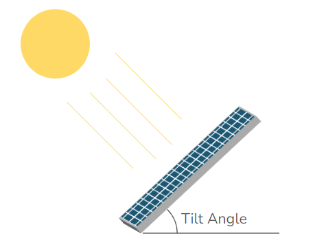
Panel tilt angle:
- For year-round maximum power, set the tilt roughly equal to your location's latitude. For better winter performance in low-light locations, add 15 degrees.
- For very high-latitude, low-sun-angle sites, you may want to optimize further, see this Solar Panel Tilt Angle Calculator.
- In snow country: a snow-covered panel produces no power, so use a tilt of at least 45 degrees (or steeper) to help snow slide off. At easily accessible sites, a lower angle can work if you sweep the panel off after significant snowfall.
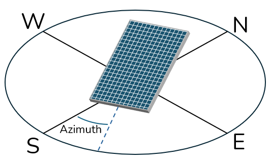
Panel azimuth direction: point the panel toward the equator, south in the northern hemisphere, north in the southern hemisphere. For low-sun locations, see this Solar Panel Azimuth Angle Calculator.
What if it doesn't work?
- Not sure which way to face it. Point it toward the equator (south in the northern hemisphere, north in the southern) at the angle from the solar calculator.
What success looks like
You've picked a mounting spot and orientation with maximum sun for your hemisphere.
2. Install the solar panel and bracket
The bracket arrives pre-assembled, but you'll adjust the mounting arms and tighten the fasteners. The instructions in the box are duplicated here.
-
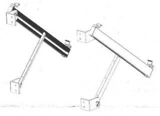
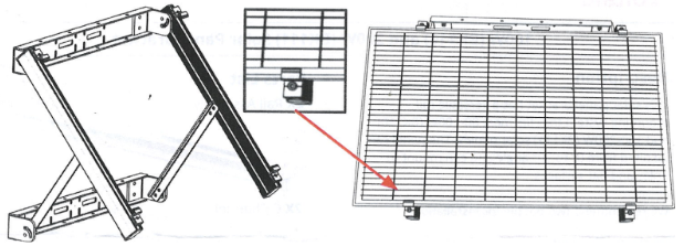
Adjust the rail assemblies so they can stand on a flat surface (you'll set the final angle later), with the rails facing inward.
-
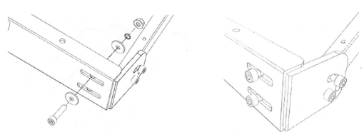
Connect the two C-channels to the rail assemblies with the eight bolts, and tighten.
-
Test-fit the solar panel on the assembled bracket by placing it under the Z-clamps.
-
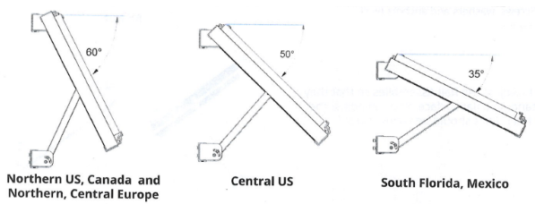
Adjust the bracket angle to your target tilt by moving the supports, and record the angle so you can track actual vs. expected performance. Tighten and secure all bolts.
-
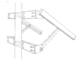
Remove the solar panel before mounting the bracket on the pole or structure. Mount the bracket with four steel straps, pointing it toward the equator (south in the northern hemisphere, north in the southern).
-
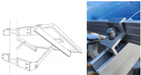
Re-attach the solar panel under the Z-clamps and tighten them.
What if it doesn't work?
- A part seems missing or won't fit. Check the "What's in the boxes" list above.
- Not sure about orientation. Follow the photos above; if still unsure, email support@clarity.io before mounting.
What success looks like
The solar panel and bracket are firmly mounted and won't shift in wind.
3. Install the battery pack
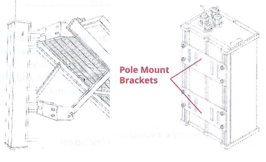
Mount the battery pack either horizontally on the solar mounting bracket, or vertically directly on a pole or structure. Which you choose depends on potential wind load, weight distribution, and your site's restrictions. Ideally, keep it shaded from direct sun as much as possible, under the solar panel, or on the back side of a light pole.
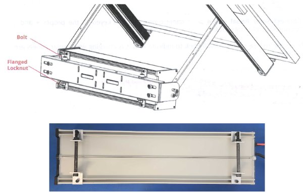
Note: If you mount the battery vertically, point the connector panel down toward the ground to protect it from rain.
What if it doesn't work?
- A part seems missing or won't fit. Check the "What's in the boxes" list above.
- Not sure about orientation. Follow the photos above; if still unsure, email support@clarity.io before mounting.
What success looks like
The battery pack is securely mounted and protected from standing water.
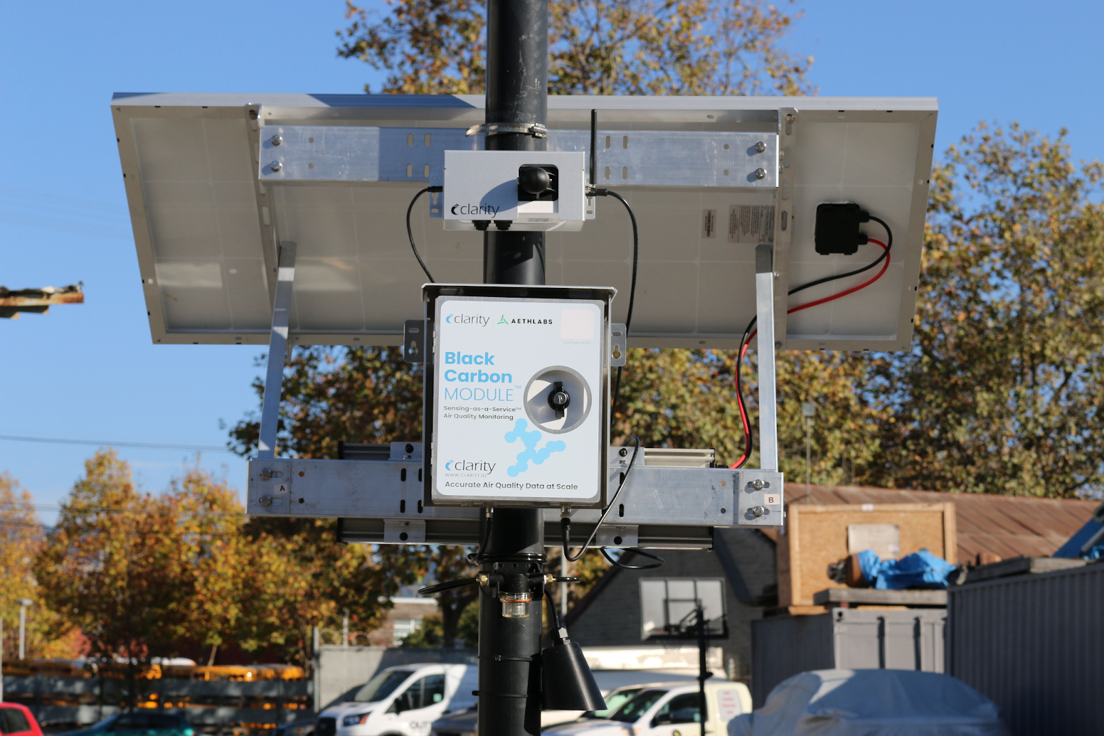
4. Connect the Node and solar panel to the battery pack
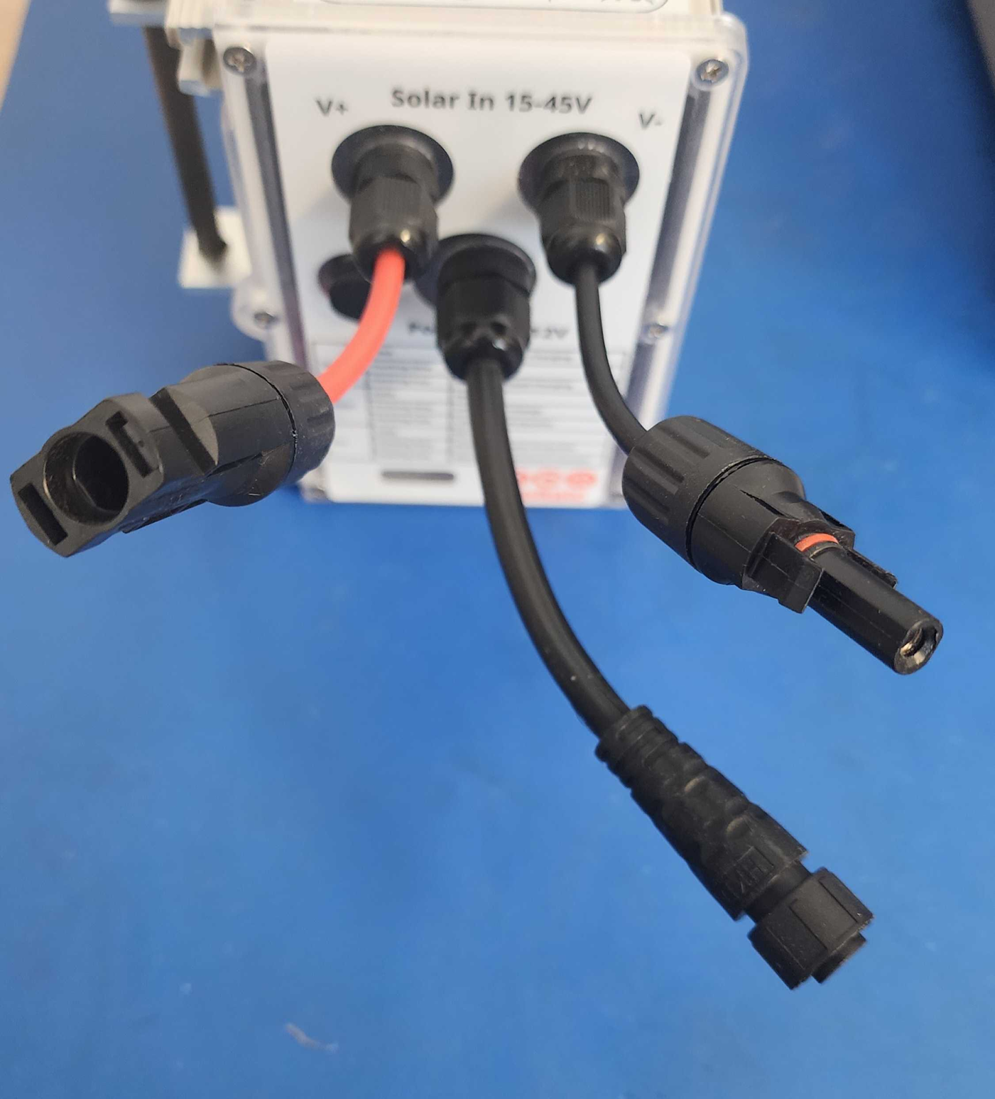
On the battery pack, the power output cable is in the middle and the solar panel inputs are on the sides (red is positive, black is negative).
The charge controller status lights are visible through the front of the battery pack:
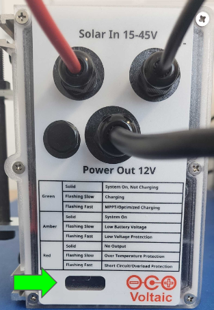
| LED (function) | Rate | Indication |
|---|---|---|
| Green, charge status | Solid | System on, not charging |
| Flashing slow | Charging | |
| Flashing fast | MPPT / fast charging | |
| Amber, output status | Solid | System on |
| Flashing slow | Low battery voltage | |
| Flashing fast | Low voltage protection | |
| Red, output error | Solid | No output |
| Flashing slow | Over temperature | |
| Flashing fast | Short circuit protection |
Note: A Node power cable must be connected to the battery pack's power output to turn the system on, and also to enable charging from the solar panel.
- Connect the Node to the battery pack power output. This turns on the charge controller, and the amber light should come on.
- Connect the solar panel to the battery pack input. Push the solar panel's MC4-style connectors into the battery pack inputs until the retainer clips latch, this also makes the connection weather-tight. The connectors are polarized, so you can't connect them backward. To disconnect later, press the retainer clips with your fingers or needle-nose pliers while pulling the contacts apart.
- Secure the wires so they don't move in the wind. Bundle them neatly and use plastic zip ties only, metal zip ties can cut through the wire insulation. Use drip loops where needed so rainwater drips off the cable before it reaches a connector.
What if it doesn't work?
- I hear the Connection Failure sound (beep beep beep). Confirm the Module was paired on the Dashboard first, then re-seat the cable firmly.
- The Module shows an alarm on the Dashboard. See Troubleshooting accessory Module alarms.
- Weak or no signal at the site. See Troubleshooting a weak signal alarm.
What success looks like
All cables are connected, the Node powers on (the amber output LED is lit), and it connects to Clarity Cloud.
You're done! Your External Power System is supplying continuous, off-grid power to your Node and Modules.
What's next
- Maintain your External Power System.
- Deploy the Black Carbon Module on the EPS.
- Deploy the Ozone Module on the EPS.
- Deploy your Node-S.
Still need a hand? Email us at support@clarity.io or create a support ticket, and our team will get back to you.
Was this helpful?